
 The tower was designed by DFW to the brief of Sir Ernest Titterton and built by LendLease behind the Cockcroft building. It was an architectural brief mainly to make the tower as elegant as possible considering its strictly engineering function – having very thick concrete walls to contain the gamma rays emitted by the 14UD belt. Its radiating particles were transmitted from the ion generating room on top onto a van der Graff belt to the deflecting magnets at the base toward small targets to be bombarded by the particles.
Function largely determined the form – of housing a 14’ diam. steel tank, so the problem was mainly sculptural. The ion generating room needed no thermal qualities other than EWT’s requirement of “…I want a gale to blow through that room”– hence the large louvres.
I have been told recently that the louvres have never been functionally opened !
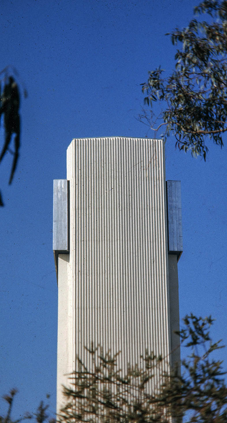
The tower’s external texture had to be strong and as maintenance free as possible, so heavy vertical ribbing seemed to be the obvious answer. The vertical corners called for visual softening and much consideration was given to the correct spacing of the ribs to avoid an apparent widening of the spaces around a radiused corner. This seems to have been achieved.
Slip form shuttering was employed but if left as bare concrete the “pours” become colour differentiated so painting was the only answer; surface treatment such as bush hammering was too expensive. The paint has already lasted 46 years and its colour makes the tower fit in with the physics colour schedule determined years before by me.
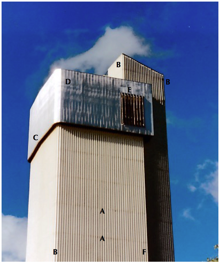
This photo shows a little more clearly the massing relationships of the main tank compartment in the centre, the lift shaft on the right and the Ion Generating room, top centre.
Concrete does not weather well due to concentration of rainwater over the surface carrying atmospheric deposits of dirt particles which stain over time. The ribbing was a way of providing shadows which mask that effect and also provide a dominant visual contrast to ‘hide’ the horizontal mould separation marks which always show at the next lift point – the marks are faintly visible at A but would have been much worse if the ribbing had not been used.
To avoid the ‘boxiness’ of the main shaft the corners were rounded which required a series of cardboard models to find the optimum variation of spacing around the curve which can be seen at B. To have left the corner as a 90º junction would have produced a visually sharp and awkward definition of the two planes whereas it now appears as if the ribs smoothly wrap around the corner, uniting the planes rather than separating them. It is an optical refinement similar in some ways to the early Greek designs of the fluting on the columns and their use of entasis. The ribbing at F is a sharp termination of the tank shaft and looks appropriate, separating itself from the lift shaft..
A further refinement was the bending of the plane at C to ‘soften’ its flatness. A curve may have been better but more expensive.
The aluminium cladding can be seen at D and it is unfortunate that the photo was taken at just the moment when the sun was just a degree or two off the surface plane magnifying the slight ‘belling’ of the panels. At any other time this effect would not be perceived.
The louvres to achieve Sir Ernest’s ‘gale’ are shown open at E, but when closed re virtually indistinguishable.
I feel very pleased that these small refinements were able to be constructed at very little cost. The tower is a dominant feature of the landscape in that area and is now a softer and more appropriate intrusion. It is, and should be sees as, a massive sculpture.